The BNC in General
To sum up what is a long story the following brief list is why we use the BNC family on our Antennas:
- They are very adaptable
- If you buy or upgrade your radio, you don’t need to buy a new antenna, just an inexpensive adapter
- They are durable and long lasting for thousands of on/off cycles
- The BNC is rated at up to 4 GHz (some manufacturers rate them up to 12GHz).
- 4GHz is much higher than the HF (135 kHz), VHF (144 MHz) & UHF (420 MHz) frequencies that most HAMS will use.
- Even the 23cm (1240 MHz) & 13cm (2300 MHz) are well within the operational specifications of the BNC.
- The connector is conservatively rated at over 200 Watts (some versions can handle 1KW). Again higher than most radios.
More About the BNC
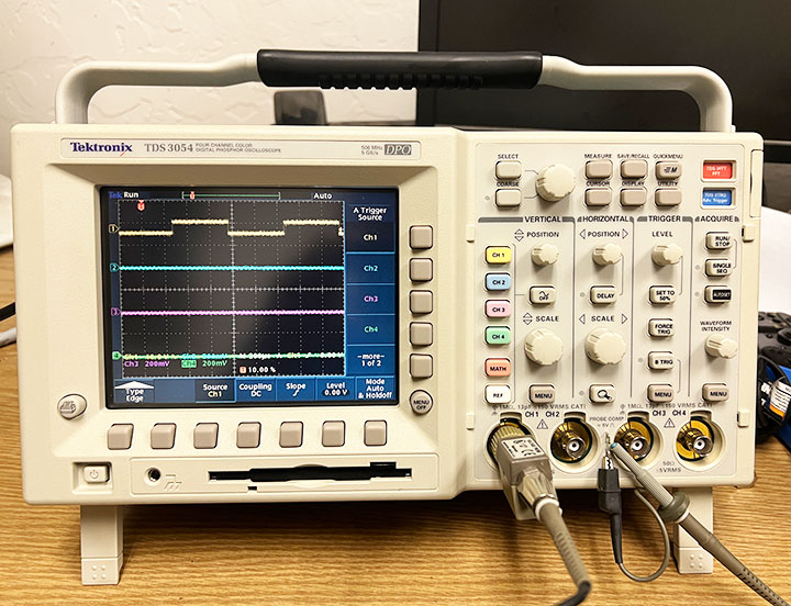
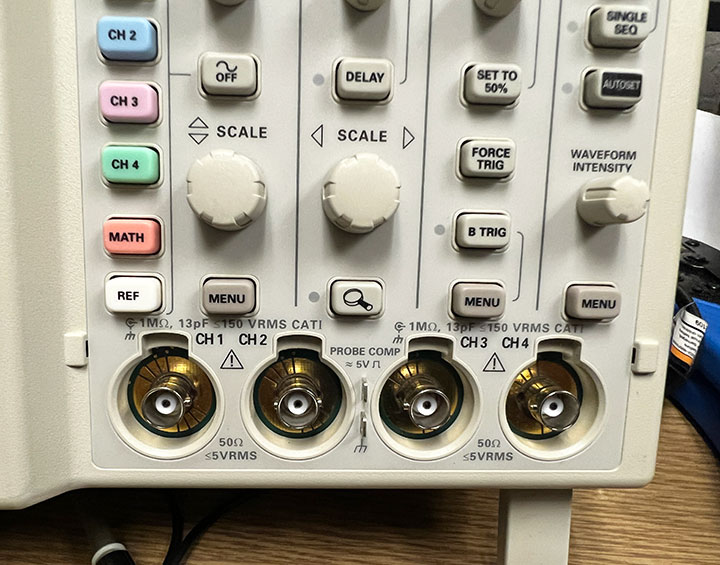
The BNC coax connector is one of the most widely used RF connectors today. It is very easy and convenient to use, and offers a very high level of performance. The BNC connector is used on test equipment for everything from oscilloscopes to audio generators, and power meters to function generators. In fact BNC connectors are used in applications where coaxial or screened cable is required, and particularly for RF applications.
The BNC connector is rated up to 4 GHz and over 200 Watts of power. All of my high level test equipment ranging from oscilloscope to spectrum analyzer to function generator employ the BNC connector.
The BNC connector has many attributes. One its chief mechanical attributes is that it uses a bayonet attachment. This is particularly useful because it provides quick & easy attachment/detachment. It also prevents accidental disconnection if the cable is pulled slightly or repeatedly moved.
The BNC is also what is termed a constant impedance connector. This means that it has the same characteristic impedance across the whole of the connector. Coax cable has what is called a characteristic impedance. Accordingly any RF signals travelling along a coax cable will not see any impedance changes as they pass through the BNC connector. This is particularly important for RF applications as it will result in few reflections and a lower level of loss.
To get more facts about the BNC Connector Click Here.
BNC development
The BNC connector was developed in the late 1940s and it gains its name from a combination of the fact that it has a bayonet fixing and from the names of the designers, the letters BNC standing for Bayonet Neill Concelman. It has also been utilized to stand for Bayonet Navy Connector in some references (it was first used by the Navy).
The BNC connector is essentially a miniature version of the C connector which was in turn a bayonet version of the N-type connector.
The BNC connector was developed as a result of the need to provide a high quality, durable connector that would be capable of being used in a wide variety of applications. Additionally it needed to be smaller than either the N-type or C-type connectors which were much larger.
BNC specifications
The specifications of the BNC connector naturally vary from one manufacturer to another and it is always best to ensure that the particular component being purchased is suitable for the intended application. However there are a number of guidelines that can be used. The connector comes in two basic types:
- 50 ohm
- 75 ohm
Of the two versions of the BNC connector, the 50 ohm version is more widely used. Often the BNC connector is specified for operation at frequencies up to 4 GHz and it can be used up to 10 GHz provided the special high quality versions specified to that frequency are used. However it is best to fully check the specifications.
The dimensions are approximately the same as for N connectors, which are adequate for 1 kW or so, but the outer conductor connection is normally made by fingers rather than a solid cylinder. Under ideal conditions you can probably run hundreds of watts, but if the connection was poor, it could result in arcing, which would lead to further degradation and probable failure.
BNC connectors have been used for a on a NASA satellite project over 30 years ago (actually the rotation was ~100 degrees, one-time) running 10 watts at VHF with no adverse effects. Hand Held Radios typically run at 5 Watts, Mobile & Base Radios up to 100 Watts. The BNC is perfect for these radios.
Basic BNC Specification Summary | |
Parameter | Specification |
Cable Type | Coaxial (Many Sizes) |
Securing | Bayonet fit |
Typical operating frequency range | 0 – 4 GHz (Some Versions up to 10 GHz) |
Diameter (Male) | 14.0 mm / 0.570 in |
Power Rating (Nominal) | >200 Watts (Some Versions up to 1 kW) |
Diameter (Female) | 11.1 mm / 0.436 in |
BNC connector formats and variants
BNC connectors come in a variety of formats. Not only are there plugs and sockets but there are also adapters and also other items such as attenuators.
BNC plugs are designed not only for the required impedance, but also to accept a particular coax cable format. In this way all the internal piece parts are compatible with the coaxial cable used. It is therefore necessary to specify the BNC plug for the specific cable to be used. Although there is some latitude, it is naturally best to select the correct cable format.
In addition to this there are straight and right angled variants. Of these the straight connectors are the most widely used, although right angled connectors where the cable leaves the plug at right angles to the center of the connector center line are also available. These are ideal in many applications where the cables need to leave the connector in this manner to ensure cables are in a tidy fashion, or where space is at a premium.
Unfortunately, right-angled connectors have a marginally higher level of loss than their straight through counterparts. This may not be significant for most applications, but at frequencies near the operational limit of the connector there may be a small difference.
The sockets or female BNC connectors also come in a number of different varieties. The very basic BNC connector consists of a panel mounting assembly with a single connection for the coax center. The grounding is then accomplished via the panel to which the connector is bolted using a single nut. Large washers can be used to provide an earth connection directly to the connector.
Some of these connectors may also use four nuts and bolts to fix them to the panel. These arrangements are only suitable for low frequency applications, and not for RF. Where impedance matching and full screening is required. Bulkhead mounting connectors where coaxial cable entry is provided are available for this. Again these are available for a variety of cable dimensions and the correct type should be used.
There are two main variants of the BNC connector assembly method:
- Compression gland type
- Crimp type
Silver plated BNC connectors will become oxidized with time, although they are still usable
BNC plug assembly
The assembly of a BNC connector will depend upon the type that is to be used. Both types require assembling wit reasonable care, and the crimp style requires a crimp tool for its assembly.
The compression gland type of BNC connector has the center pin of the connector which is usually a solder pin and the braid and sheath of the cable are held by an expanding compression gland fixed by a nut at the rear of the connector. This type of connector by its nature can handle a (limited) range of cable sizes and requires no special tooling to assemble. This makes it ideal for small quantity production, either for one off cables for laboratory use of for limited production runs.
The crimp BNC connector has the center pin which is normally crimped to the center conductor. This crimped pin is then pushed into position through an inner ferrule which separates the inner insulation sheath and the braid of the cable. An outer ferrule is then crimped over the braid and outer insulation which fixes the cable to the connector. Greater accuracy is required for the crimp style connectors and therefore the correct connector variant must be chosen for the cable being used.
The results of these factors may result in a crimp style connector not being practicable for some cable types. In addition to this the assembly requires the use of the correct crimping tools to ensure that the connector is correctly crimped. While these connectors are always preferred for large production runs because they are much faster to assemble, it is not possible for them to be reworked for obvious reasons.
For both styles of BNC connector it is essential that the precise amount of insulation is stripped from each section to ensure accurate assembly and the required RF performance.
There are many style of adapters available for the BNC. In addition to this a variety of inter-series adapters are available to enable transitions to be made between different connector types. These inter-series connector adapters can be very useful as it is not uncommon for two or more varieties of connector to be used in a laboratory or work area.
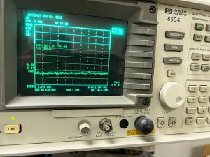
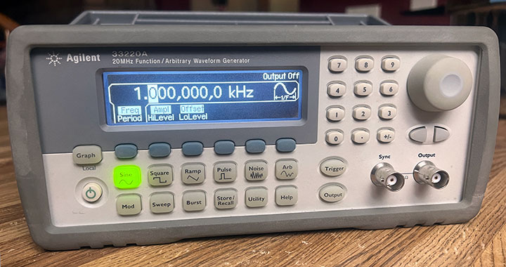
BNC Connectors are Dependable!
As the photos in this post show, most of our high end test equipment utilizes the BNC Connector. They are indeed robust and reliable not to mention long lasting. We have our highest confidence in them!
The BNC connector is probably the most widely used RF connector today. It is easy and convenient to use, it is robust, cost effective, and relatively easy to assemble, although a little care is needed (as is the case with all connectors). As a result, the BNC connector has become one of the go-to standards for RF connectors that are used in the electronics field today.