While you may have no problem identifying which standard polarity RF connectors are pin (male) or socket (female), do you find it difficult to identify the gender of reverse polarity connectors? If so you are among a large group. Don’t worry, and remember, you are certainly not alone.
In addition to the gender issue, it’s easy for us all to get confused by the many different types of RF connectors used in HAM Radio, Test Equipment and Electronics Equipment in general.
When you are using HAM Radio Antenna Connectors and trying to connect your devices, you may sometimes wonder which connector type you have and/or which connector type you need.
In this short article, I will explain the difference between center pin (male) and center socket (female) RF Connectors. We will also cover their polarity—standard or reverse (RP). We will include a number of images to help you identify the various types of connectors that are commonly used.
Basic Background
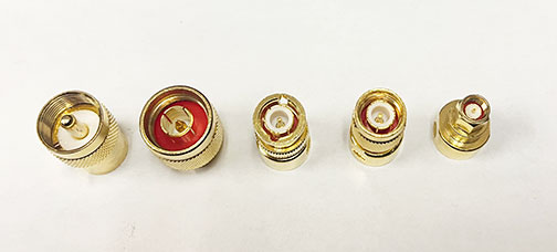
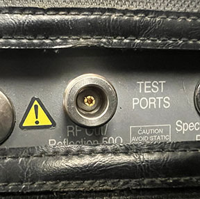
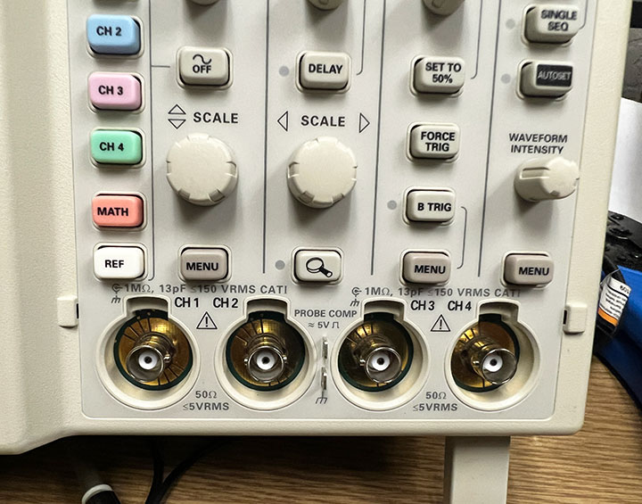
RF (radio frequency) connectors are commonly used on many different products, such as Antennas, radios, surge protectors, enclosures, coaxial cables, and test equipment. These connectors come in a variety of types. The most common connector types are the 5 types shown in the group picture above and in the individual descriptions below.
Gender and Polarity
When using HAM Radio Antenna Connectors and you’re trying to identify pin (male) and socket (female) connectors, you may find it useful to keep in mind the following:
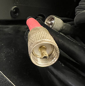
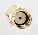
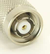
When mating two connectors, it is important to ensure that both connectors have the same polarity. For example, both should be RP-SMA. Typically, RF plugs are pin (male), and the threads are on the inside of the shell.
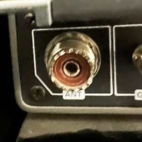
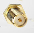
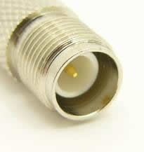
Typically, RF jacks are socket (female), and the threads are on the outside of the shell.
The shell of a plug (male) typically covers the shell of a jacket (female).
Building off of these concepts, here are some more helpful descriptions:
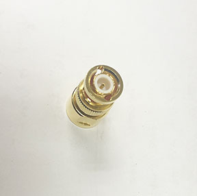
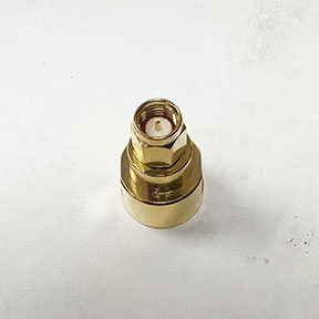
A standard polarity plug (male) has a center pin that sticks out from the middle, and
the plug’s shell has threads on the inside.
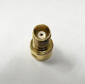
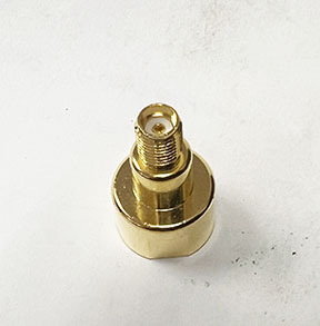
A standard polarity jack (female) has a socket in the middle designed to receive the
pin from the plug (male), and the jack’s shell has threads on the outside.
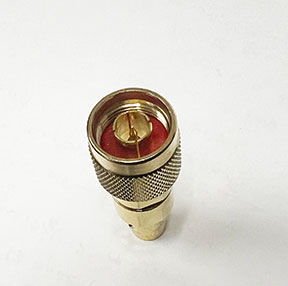
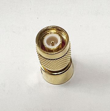
A reverse polarity plug (male) has a socket in the middle designed to receive the
pin from the jack (female) connector, and the plug’s shell has threads on the
inside.
Remember, reverse polarity jack (female) has a center pin that sticks out from the middle, and the jack’s shell has threads on the outside.
Remember This!:
A standard polarity jack (female) has a socket, whereas a reverse polarity jack (female) has a pin.
A standard polarity plug (male) has a pin, whereas a reverse polarity plug (male) has a socket.
Our goal in this article is to give you the descriptions, information and images to help you understand the differences between the different connector types and the relationships of polarity and gender.
The following descriptions and images will help you identify the 5 types of connectors most commonly used in radio as well as their genders: